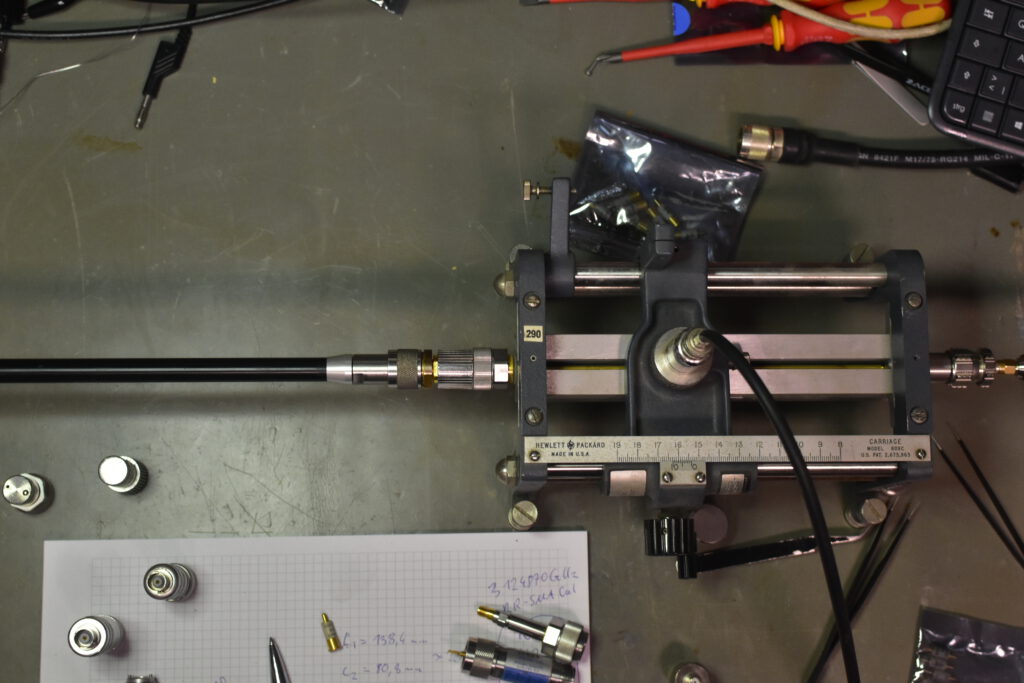
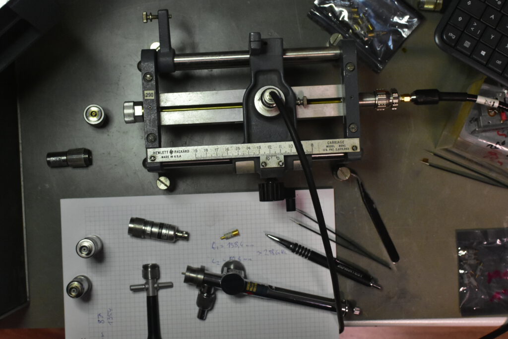
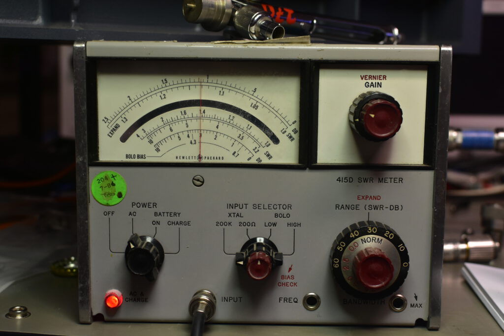
Last year I picked up with a whole bunch of other measurement gear two slotted lines (HP 816A & HP 805C) with the corresponding SWT Meter HP 415D and a few crystal detectors.
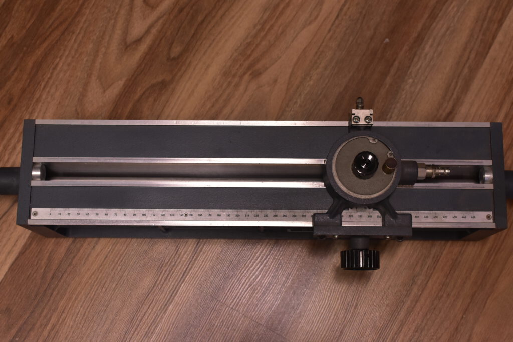
Slotted lines did serve as a tool for RF measurements predating the earliest network analyzers, enabling analysis of signal characteristics within transmission line. This is achieved by inserting a movable probe along the – cut open – line (hence slotted). This allows for determination of voltage standing wave ratios, reflection coefficients, unknown impedance determination and frequency estimation.
This is achieved by being able to read / measure the absolute position of the voltage measurement point on the transmission line. By this the wavelength between peaks of the sine, or negative peaks, can be determined.
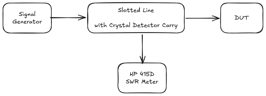
The measurement setup looks alike as the following:
Measuring Freuquency
For measuring the frequency I applied a defined frequency with the signal generator and were able to obtain those results:
Signal Generator generated Frequency: 3124.87 GHz Counter measured to 3124.873 GHz (GPSDO)
Third Party Probe with MA41453 Diode
SpeedOfLight / (((162 millimeters) - (113 millimeters)) * 2) = approx. 3.059106714 GHz
Third Party Probe with 1N23A Diode
SpeedOfLight / (((162.4 millimeters) - (113.9 millimeters)) * 2) = approx. 3.090643897 GHz
HP 447B:
First to Second Peak.
SpeedOfLight / (((162.3 millimeters) - (114.4 millimeters)) * 2) = approx. 3.129357599 GHz
Second to First Peak
SpeedOfLight / (((162.3 millimeters) - (114.2 millimeters)) * 2) = approx. 3.116345717 GHz
Measuring reflected wave
For measuring e.g. the reflection via a 3dB Attenuator the procedure was as follows:
1. Search for the first peak of the standing wave via moving the probe
2. Adjust Range & Gain Dial till the meter reads 0 / SWR 1.0
3. Connect Attenuator
4. Search for the first peak of the standing wave via moving the probe
This has to be done again, as the phase offset of the reflected wave changes as the incident wave gets „later“ or „farther away“ reflected.
This effect can also be used to estimate the phase offset for a given DUT.
5. Read attenuation (Double way)
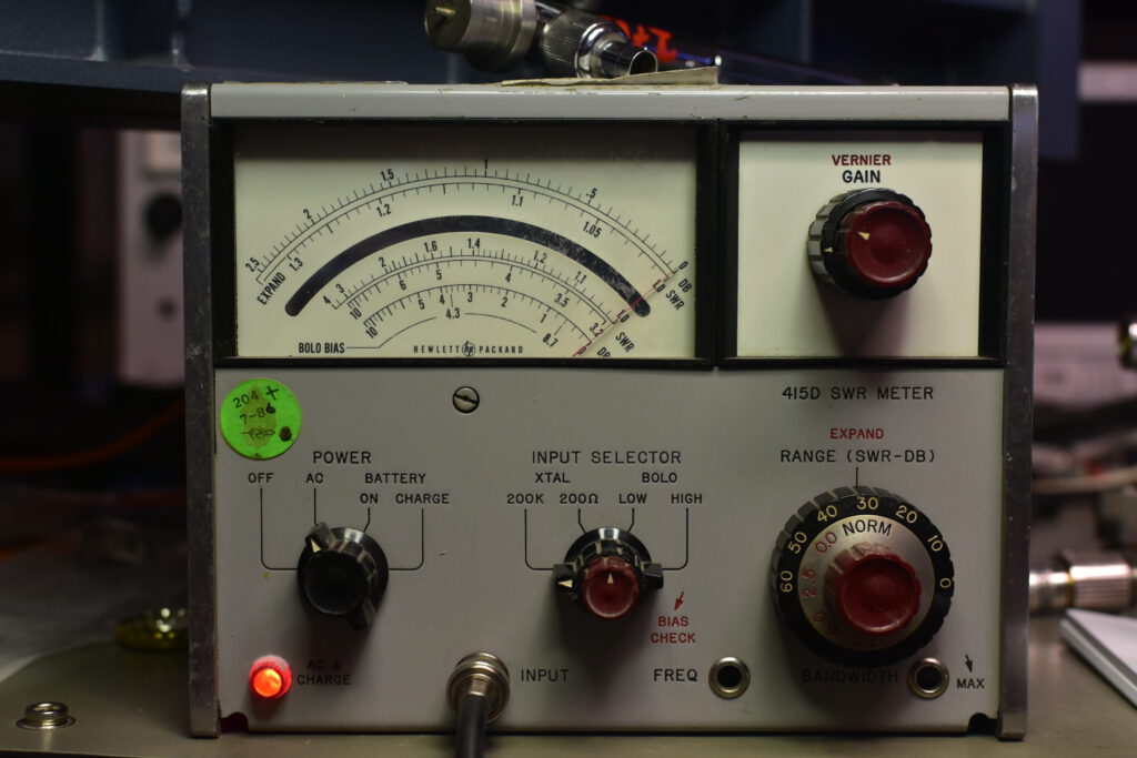
The procedure can be repeated with 50 Ohm Termination or sliding load (HP 905A conveniently available) to measure the actual reflection coeffiecient of the attenuator.
This is heavily impacted by the probe distance to the slotted line, which can be adjusted depending on the setup. (My thirdparty probe can adjust it and the HP 805C integrated one too)