
Deep into repairing the 2nd Advantest R3265A with the faulty power supply and replacing the 2nd LO with alternative parts, I’ve discovered an issue with my HP 8560A spectrum analyzer.
Technical specifications & features
The HP 8560A is a high-performance portable spectrum analyzer (by the words of the 90s) designed for RF design and service applications. It offers an frequency range, covering 50 Hz to 2.9 GHz in DC-coupled mode and 100 kHz to 2.9 GHz in AC-coupled mode, making it suitable for a wide range of measurement needs. With a sensitivity of -130 dBm, it can detect weak signals with precision. The analyzer provides flexible resolution bandwidth options ranging from 10 Hz to 1 MHz, allowing users to tailor their measurements to specific requirements. Its dynamic range reaches up to 128 dB, ensuring accurate and detailed signal analysis.
The HP 8560A features demodulation capabilities, supporting both AM and FM modulation, making it versatile for different applications. With a respective reflection bridge like the ZRB-2 it allows S11 & S21 parameter measurements. The tracking generator option (Option 002) further enhances its capabilities, providing a frequency range from 300 kHz to 2.9 GHz with excellent tracking drift performance.Overall, the HP 8560A is a reliable and versatile spectrum analyzer that offers excellent sensitivity, frequency coverage, and measurement capabilities for my hobbyist usage 🙂
The issue
Since I haven’t had the spectrum analyzer running in a while I did the calibration routine. Without any issues the cailbration menu stated no issues and successfull calibration.
I used this opportunity to hook up this spectrum analyzer also to the GPSDO distribution amplifier. Therefore I wanted to do a reference measurement and see if my fequency counter and spectrum analyzer would show the same result for the 10 MHz reference signal.
As I tried to measure the residual phase noise out of curiosity I stumbled across the problem:
The spectrum analyzer would show no amplitude whatsoever. But only with a relatively low frequency of interest window. Taking measurements of the 300 MHz calibration signal revealed no issues only the 10 MHz reference signal. Another restriction was that the issue only shows on span settings below 1.1 MHz and above 100 kHz.
My first diagnosis step was looking at the 1st local oscillator output which is reachable from outside of the housing.
In these two plots you can see on first hand that the spectrum analyzer sweeps correctly the local oscillator with a span of 1.1 MHz as configured on the HP 8560A. But on the second plot in red it’s visible that – with a span setting of 1 MHz on the HP 8560A – the local oscillator starts jumping.
Why ? … and how does a spectrum analyzer even work ?
The meaning and purpose of a spectrum analyzer is to make – usually – RF power against frequency visible.
Why do you ask – because often you want to ensue specific power levels at certain frequencies e.g. a radio transmitter needs to have a quite narrow signal to allow multiple signals in a close range like radio stations. Or to detect unwanted frequency components coupled to other cables, amplifiers etc. Like humming music amplifiers if you plug in your cheapo off-brand switch mode power supply and the switching frequency is coupled. Or visualize that the energy of your microwave oven is actually not that far away from your WiFi signal …
A primitive approach would be to build a tunable filter and observe the power levels at the shifting window of interest (resolution bandwidth). But as soon as you would go out and have a look for wideband tunable filters you will hit the wall. That isn’t easy at all. Whats easy is to build up a high quality filter at a fixed frequency e.g. crystal filters.
RF Mixers
Radio frequency mixers want to behave as much as the mathematical multiplication of two frequncies.
If you would be to solve a multiplication of two cosines you would rather fst get to two results: The sum and the subtraction of the two „miexed“ frequencies. This leaves you with a perfect situation if you want to get a higher frequency signal down.
Down-conversion is the process of mixing a high frequency signal of interst with another high frequency signal and resulting in a intermediate frequency which gets filtered out the sum of the frequency. So you are left with the subtraction. Usually the mixing frequency is called local oscillator and the product intermediate frequency.
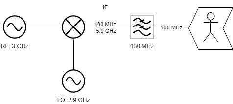
By altering the local oscillator frequency in a special manner you could create a control loop with the RF input frequency to keep the intermediate frequency stable at a certain value.
For example by mixing a input frequency range (RF) of 50 Hz to 2.9 GHz with a 3.0 to 6.8 GHz local oscillator you could always keep the intermediate frequncy at 3.9107 GHz.
Function description and block view
But because 3.9107 GHz is a little high for further processing (e.g. RF detection video bandwidth filtering etc…) we have three additional mixing stages to bring the frequency down to 10.7 MHz where the high quality crytsal filter sits.
Always in between make up amplifiers to bring the signal back up after mixing and filtering.
But the problem of my faulty unit is caused by different span setting so I dug down to
see how the HP 8560A operates the sweep function.
Rollers, offsets and Yttrium and how to sweep ?
The main oscillator of thie spectrum analyzer (for the 1st local oscillator) consists of a
Yttrium Iron Garnet tuned oscillator. The YIG filter is a special filter which works
well at relatively high frequencies.
In technical terms, a YIG (Yttrium Iron Garnet) filter works based on the principles of magnetic resonance. Here’s a concise explanation:
- YIG Material: A YIG filter contains a crystal made of Yttrium Iron Garnet.
- Magnetic Field: It’s placed in a magnetic field that can be adjusted.
- Resonance Frequency: When exposed to the magnetic field, the YIG crystal adjusts its resonance frequency. This frequency is extremely sensitive to the strength of the magnetic field.
- Frequency Selection: By varying the magnetic field’s strength, the YIG filter can select a precise frequency from a range of incoming signals. It allows signals very close to its tuned resonance frequency to pass through while attenuating others.
In essence, a YIG filter exploits the YIG crystal’s ability to change its resonance frequency with the applied magnetic field, enabling it to act as a highly precise and tunable filter for specific radio frequencies.

YIG filters have a draw-back – due to the relatively huge magnetic flow you need to control the sphere you can’t change the resonance fast. But with a smaller secondary coil – usually called FM coil – you are able to control it even faster and more precise.
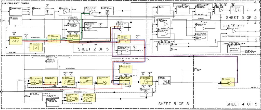
But to control the different spans there are four different oscillators:
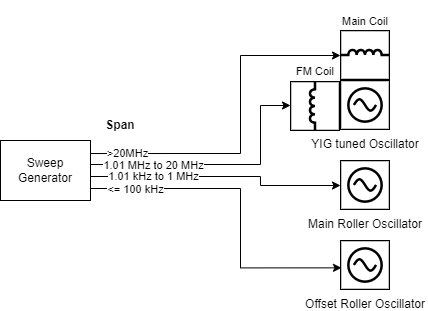
All four oscillator collaborate in one big phase locked loop. Depending on which oscillator sweeps the others stay fixed and are locked in loop. As you can see in the upper diagram there is exactly one oscillator responsible for the span setting between
100 kHz and 1 MHz.
Hallo,
ich habe bei meinem HP8560A genau das gleiche Problem. Mit der Fehlermeldung Error304.
Trotz Servicemanual und kpl. Schaltbild bin ich dem Fehler noch nicht auf die Spur gekommen
Hi Uwe,
Ich hätte noch keine Lust mich bisher um den Speki zu kümmern. Es gab’s zwischenzeitlich andere Projekte. Aber meine weitere Analyse mit dem CLIP das ich mir besorgt habe, wäre in die Richtung gegangen den Main Roller Oscillator bzw. den Sweep Generator in dem Fall zu untersuchen. Ich bin mir fast sicher, dass man dort etwas finden sollte.
Ich würde damit starten den im Diagramm (AG) genannten Main Roller Oscillator durchzumessen, also schauen ob bei entsprechender Span Einstellung eine Sweep Spannung bekommt und entsprechend die Ausgangsfrequenz variiert.
Da der Fehlercode bei mir so nicht Auftritt vermute ich, dass der tatsächliche Defekt eventuell marginal unterschiedlich ist.
Viele Grüße und Erfolg
Sebastian N.