
I entered an auction for two visually flawless Tektronix Type 109 pulse generators, though uncertain of their operational status.
The Tektronix Type 109 Pulse Generator is a fast risetime pulse generator similar to the pulse generator section of the Type 110. The Type 109 is capable of producing pulses of different widths, calibrated amplitudes, and polarities for use in driving and testing the response of devices operating in the nanosecond region.
Instruction Manual Type 109 Pulse Generator Tektronix / 070-299[1]
Upon arriving at my place, I tried starting up the devices, aiming to assess their functionality. However, despite the successful startup, a critical observation surfaced: the pulse generator failed to output any pulses, indicating a functional discrepancy.
At that time I also made the mistake of generating too short pulses which my small oscilloscope wasn’t able to display.
This unanticipated outcome prompted a shift in focus from the general startup issues to a specific concern regarding the absence of output pulses.
I referred to the instruction manual, which not only contains a circuit description but also includes maintenance and troubleshooting guides. The fundamental operational principle involves a multivibrator oscillating between 275 Hz and 360 Hz. This alternating current signal drives an amplifier that, in turn, switches a transformer coil. The secondary single winding coil is wound around a mercury-wetted reed relay.
The term „mercury-wetted“ might induce a momentary pause. To provide context, during that historical period, fast switching field-effect transistors and other advanced RF semiconductors we have today were nonexistent. The test and measurement industry stood on the precipice of transitioning from tube technology to semiconductors. This particular device exemplifies that transitional phase, featuring a full and half-bridge diode rectifier alongside a voltage regulator tube.
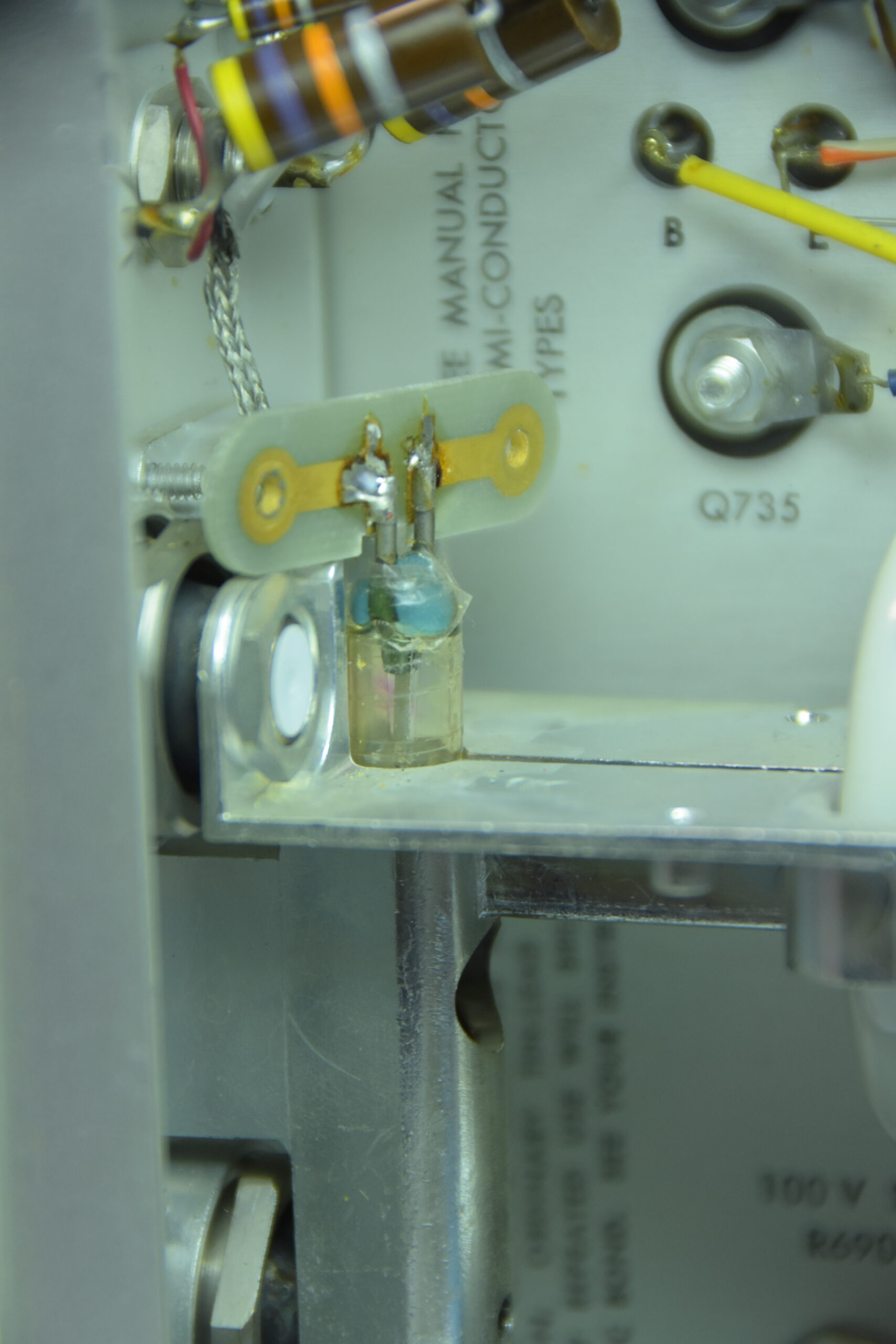
In this context, the most effective method for generating a pulse with a rapid rise time was to utilize a reed relay for switching as the technology of the time lacked alternatives like fast-switching field-effect transistors. However, a conventional reed relay posed challenges due to substantial bouncing. The solution to this issue lies in the „wetted“ contacts with mercury.
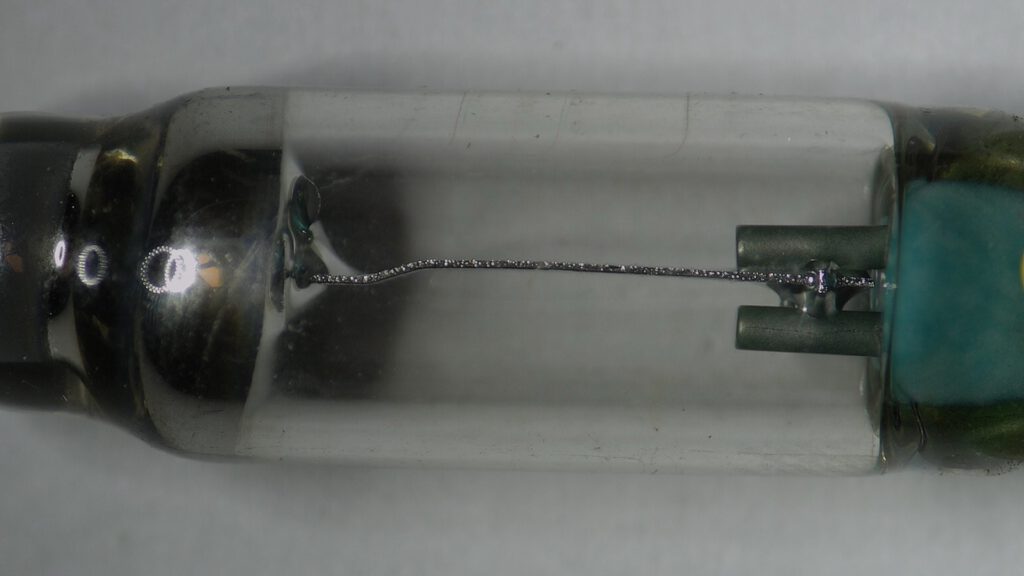
The reed relay is responsible for switching between two of the „inputs.“ The concept involves utilizing a variable-length coaxial line as a charged network, which undergoes discharge facilitated by the mercury switch. The pulser allows the charging of these two lines with voltages of up to 50V or, alternatively, with an external voltage reaching up to 300V. As an alternative to the charged line a charge-network of two different values was available.
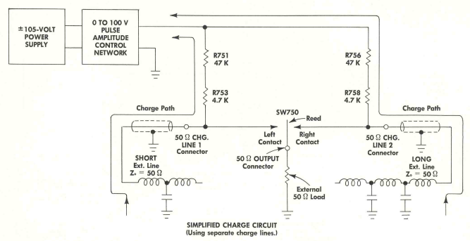
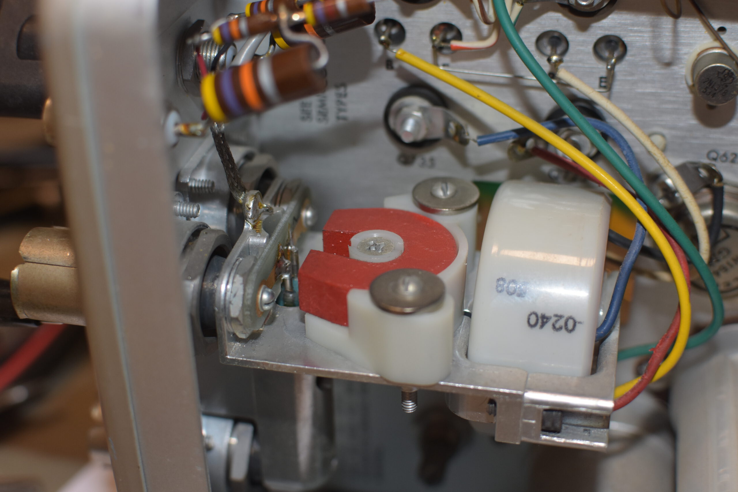
The mercury switch assembly incorporates a permanent magnet alongside the transformer to facilitate switching and establish a bias for the reed relay. It is imperative to fine-tune this bias to ensure the optimal conditions for the mercury relay to engage and work properly at all.
Adjustment and testing
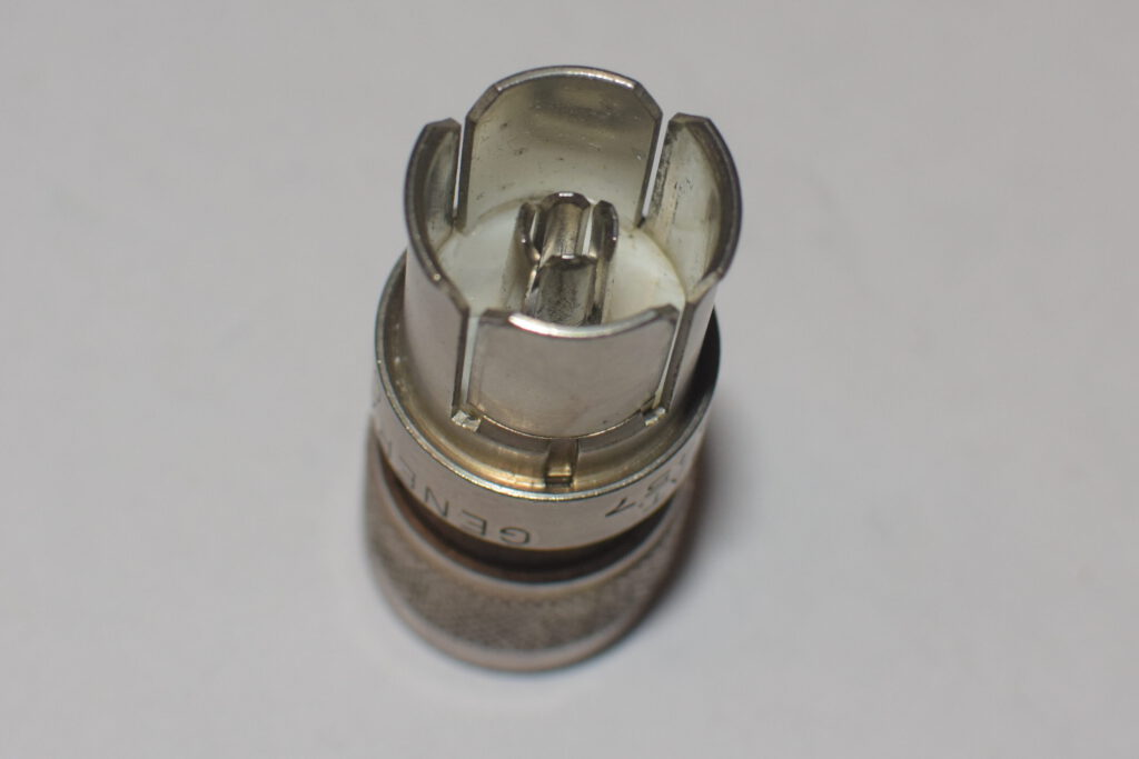
Whilest talking about the adjustment procedure a short look at the rather interesting connector type at that device.
The Type 109 utilizes the General Radio Co. GR874 genderless (hermaphroditic) coaxial RF connector, which establishes a mechanical connection solely through the friction of tightly plugged lugs.
The manual provides a detailed explanation of a testing circuit that generates both negative and positive pulses at the output. This setup allows you to trigger rising edges on an oscilloscope and inspect the switching between charge lines one and two for jitter-free performance. The manual guides you to a – hopefully – bridge-free switching experience. In case the reed relay is worn out or has other defects, it may cause a short circuit of the two input charge lines while switching.
In accordance with the manual’s instructions, I fine-tuned the magnet bias by loosening the screws and adjusting its position from left to right, maneuvering it closer or farther away from the mercury-wetted reed relay.
I adjusted it to the best of my ability, although uncertain about the ideal appearance on the oscilloscope, given the somewhat ambiguous reference image in the instruction manual. I got it as far as the relay switching at all, which results in a rather loud buzzing of the reed relay switching at 300 cycles a second.
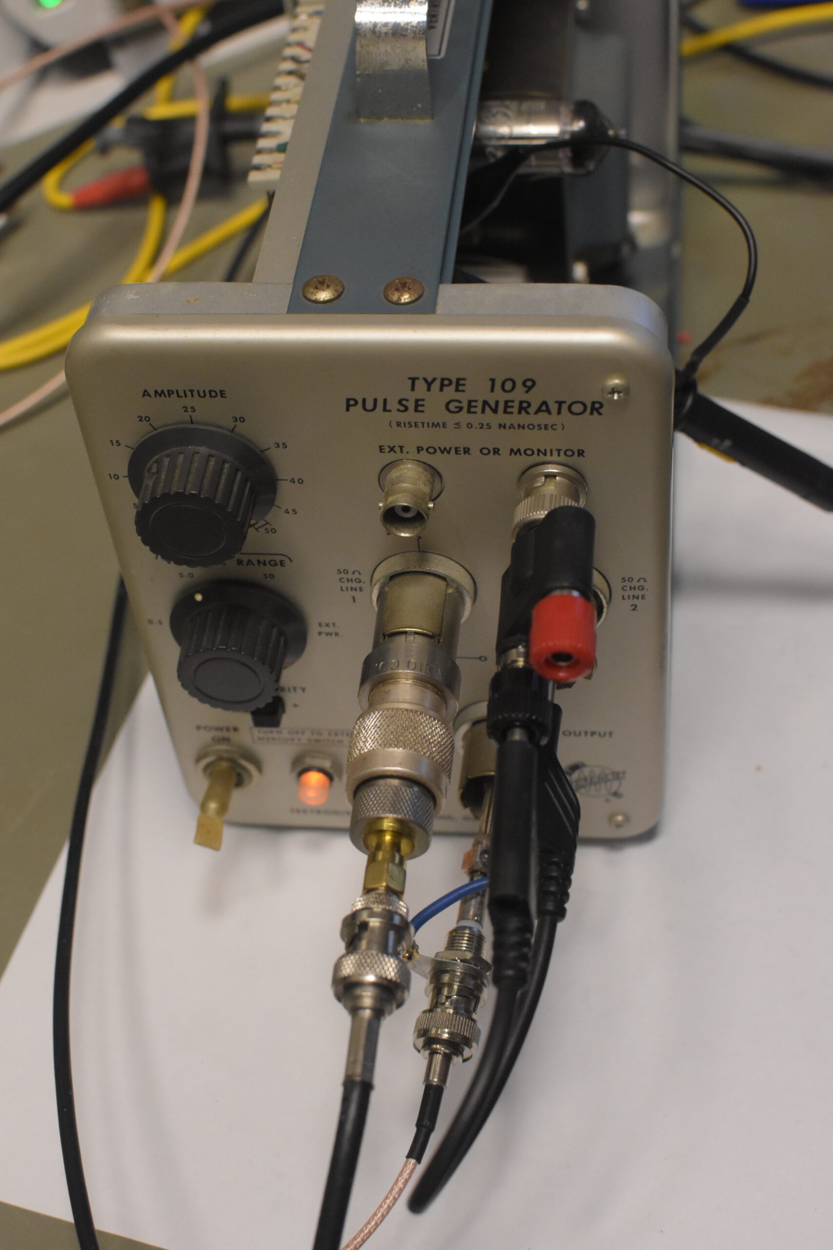
I proceeded to modify my testing configuration. Connecting a 5-meter-long RG58 coaxial line with multiple adapters to the charge line 1 connector on the device, I intentionally short-circuited the second charge line input. My objective was to eliminate the secondary pulse, allowing for the exclusive observation of one pulse type, primarily due to a shortage of GR874 adapters.
In adherence to the manual’s guidance, I discovered that it is entirely acceptable to insert a 4mm laboratory connector into the GR874 socket.
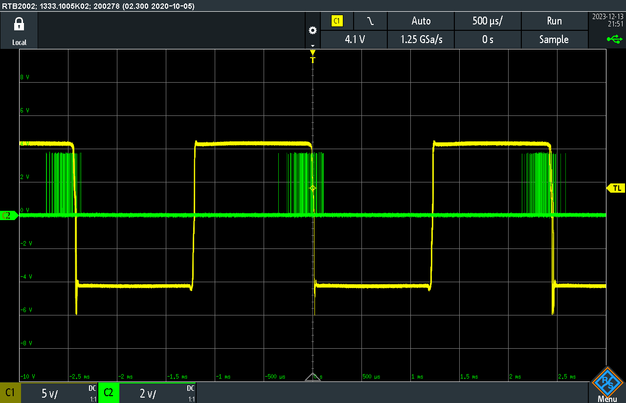
The oscilloscope screenshot displays the drive clock of the mercury-wetted reed relay, tapped from one of the power transistors driving the transformer, along with the output pulse into a 50 Ohm load. Upon closer examination and triggering, a pulse of comparable length to the charge of the 5m coaxial line cables would become apparent. However, due to the switch’s age, there is jittering during the switching process. This explanation, though formulated without the aid of a working reference unit, provides a reasonable understanding of the observed behavior.
While a certain level of jittering is considered normal in mercury-wetted reed relays[2], the Tektronix Type 109 is specifically designed for use with sampling oscilloscopes. These oscilloscopes necessitate a relatively continuous signal to function effectively. The promotion of the Type 109 for such applications implies an expectation of minimized jitter to ensure compatibility with the requirements of sampling oscilloscopes.
Unfortunately, in the second unit, the reed relay has deteriorated to the point where manual attempts to activate it by placing it in front of a powerful neodymium magnet prove unsuccessful. Despite this setback, the story takes a positive turn as I stumbled upon a similar-looking single-pole, double-throw mercury-wetted reed relay[3] in the inventory of a reseller specializing in old electronic stocks. Notably, this relay shares not only the same external appearance but also features identical contact shapes and sizes within the glass capsule. This discovery presents a potential solution to the challenges posed by the worn-out relays.