
Since a few months I’ve now had three Wiltron 610C and one Wiltron 610D lying in the corner.
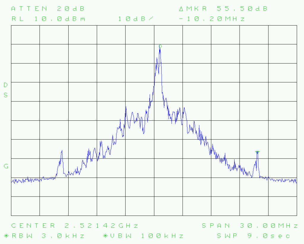
The main reason to acquire them was – apart from being cheap – to be able to test and verify the performance fo the Advantest R3265a performing up to 8 GHz.
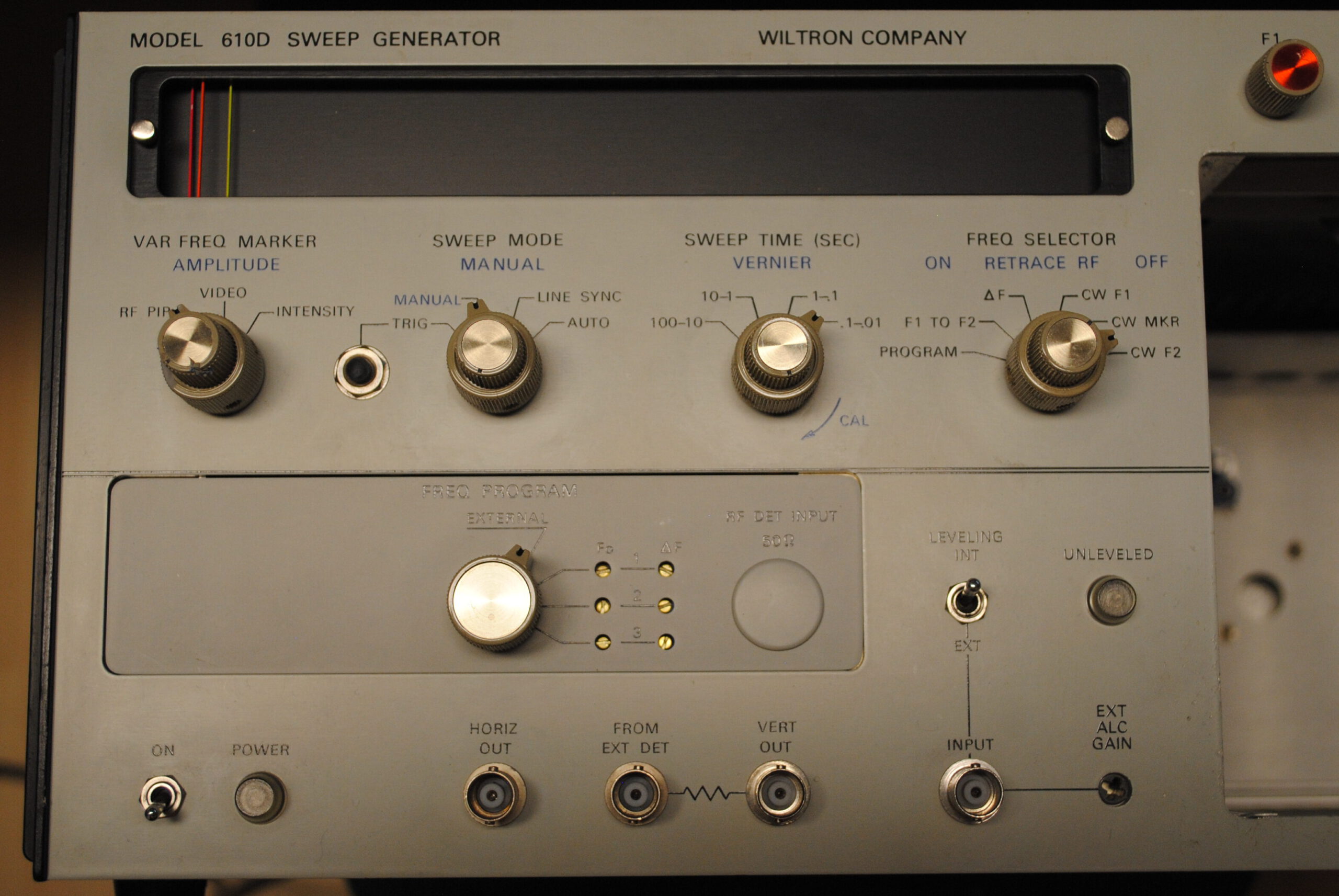
The 610 series sweep generator was used to characterize RF circuits by sweeping in a frequency region of interest and optionally logarithmically detect the output level (basically S21 parameters or S22 with an reflection bridge). The 610 can handle the sweep timing and makes the horizontal and vertical (if equipped with a RF detector) deflection available for an oscilloscope in X/Y mode.
Some variations could be hooked up to a plotter.
The Wiltron 610C comes with options from 100 kHz up to 18 GHz. With the pile of 610Cs five RF plugins came along:
- Model 61083C: 10 MHz to 1220 MHz (13dbm)
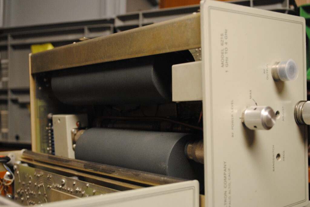
- Model 6215: 1 GHz to 4 GHz
- Model 6219: 2 GHz to 8 Ghz
- Model 6223: 4 GHz to 12.4 GHz
- Model 6130C: 12.4 GHz to 18 GHz (9 dbm)
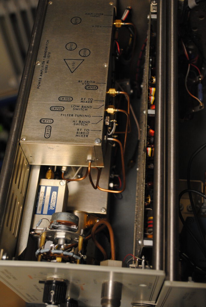
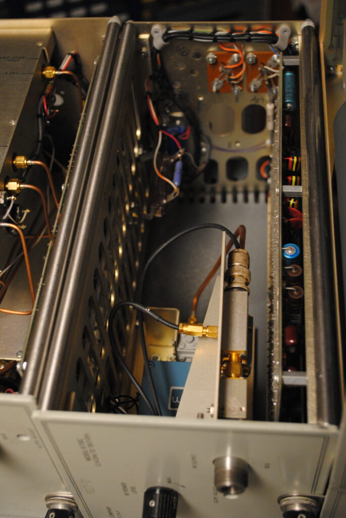
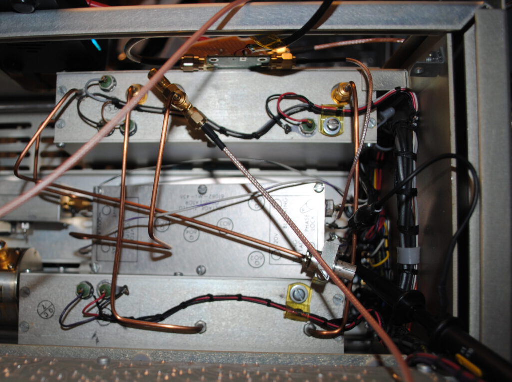
For example the 10 MHz to 1220 MHz has a voltage controlled oscillator operating between 10 MHz and 650 MHz which gets either directly – via a bandswitch – fed to the output amplifier and level control or mixed with a static oscillator operating at 650 MHz and filtered by a lowpass at 650 MHz and thus generating the higher frequencys up to 1220 MHz.
From the circuit diagram a optional phase lock can be retrieved, but I couldn’t find any documentation about such a feature or option.
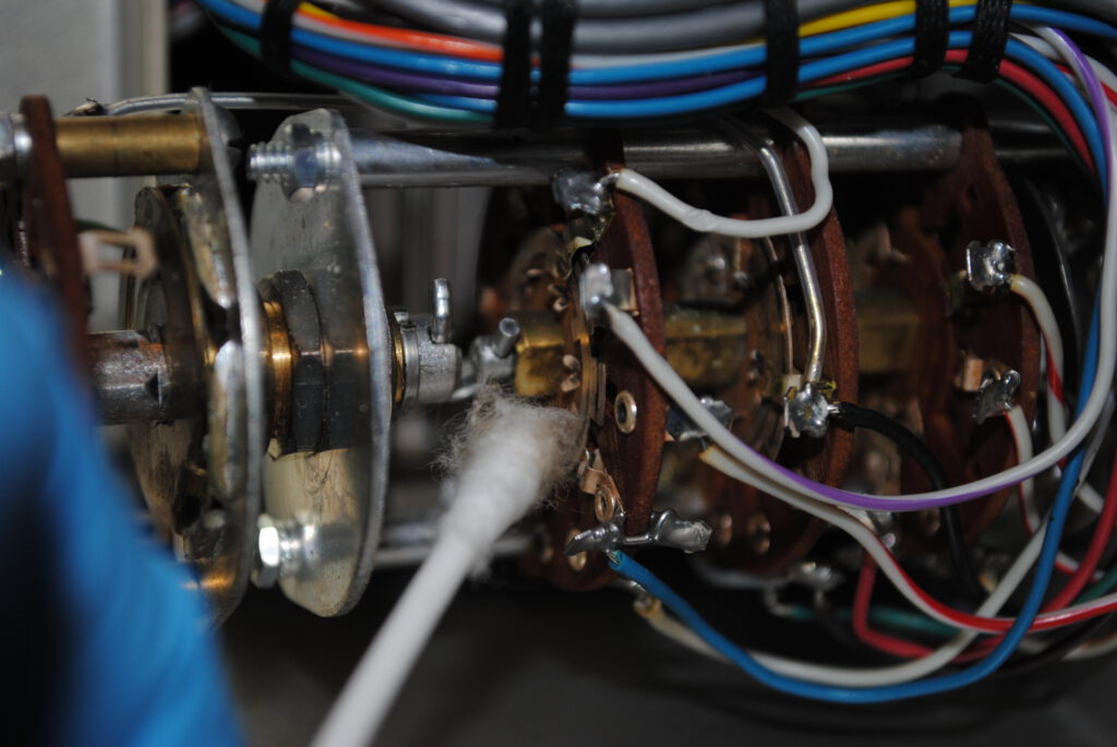
One of the devices was equipped with a birdie generator which produces harmonic markers at either 1, 10, 50 or 100 MHz around the ceneter frequency (fc+/- birdie frequency).
All of the devices come with frequency- (only external – ac coupled signal onto voltage control signal of the internal oscillator) and amplitude modulation (internal 1 kHz or external).
The output level can be controlled by an external control voltage – as well as the freuqency itself.
The frequency can be controlled absolutely or with dual parameters (operation frequency an a delta frequency input around the operation frequency).
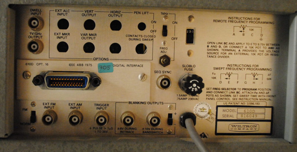
The model 610D has a GPIB option (mine so far doesn’t work, doesn’t take over the values).
During the initial start-up and warm-up I noticed a quite hefty drift of te outpt frequency without operating in any of the sweep modes – only static programmed freqeuncy. I began to research the issue a little further.
The sweep generator added a lot of noise to the voltage control input of the oscillator module. The sweep generators for the different ranges are all free running. It boils down to the voltage controlled oscillators being drifty.
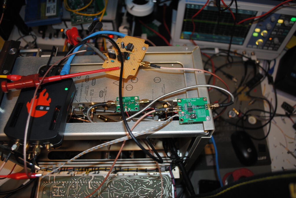
Because I red something about the phase lock option on this oscillator, I tried to use a redpitaya with some operational amplifiers as a digital servo. Controlling the oscillator against a known frequency standard (until then a crystal oscillator on the redpitaya board).
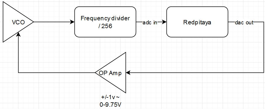
For the servo loop on the FPGA board, I tried this project on github but I kept getting crashes in the python Qt UI. (I think the service on the redpitaya crashed).
So far I gave up on this topic, those generators are enough to ‚generate‘ something at those frequencies but its not enough to link it to the spectrum analyzer.