
A few years ago, I purchased a spectrum analyzer manufactured by Advantest. The main reason for my purchase was its broad frequency range, spanning from 100 kHz to 8 GHz, and its EMI measurement capabilities. However, I haven’t had the opportunity to use it for anything other than testing some switching regulators and measuring conducted emissions, as well as validating Wiltron sweep generators.
Recently, I attempted to develop a wrapper/driver to integrate the spectrum analyzer with TEKBOX’s software EMCView. During this process, I conducted some additional tests and, unfortunately, discovered an issue. It’s possible that I may have broken the device in the process.
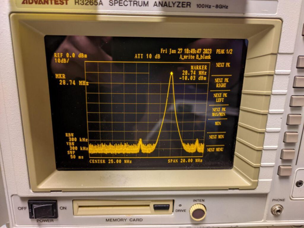
As shown in the attached picture, the frequency displayed by the marker on my spectrum analyzer is not at 25 MHz, despite being calibrated to that frequency. I posted my issue on the eevblog forum, but due to my limited information and lack of experience with the inner workings of spectrum analyzers, I received no help. In an effort to resolve the issue, I contacted the original seller and inquired about repair options.
Unfortunately, the seller was unable to repair the device but offered me another defective R3265A as a replacement, which I could use to swap modules and attempt to repair the issue myself. At that time, I conducted further research and stumbled upon a German blog post that described a similar issue. The post explained that the 2nd LO generates 3810 MHz, and the VCO is controlled via a coupled feedback loop, which is mixed with 3800 MHz. The resulting difference (10 MHz) is then phase-compared to a reference.
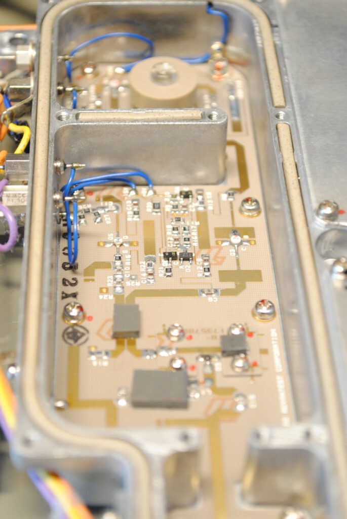
The assembly responsible for generating the frequency of 3800 MHz (and mixing) is the THD296 ceramic PCB, which is manufactured using silver ink or a similar material that oxidizes over time. As a result, the trace resistance can grow, resulting in the generation of no reference frequency for the phase detector. This causes the VCO to drift upwards and hit the upper boundary.
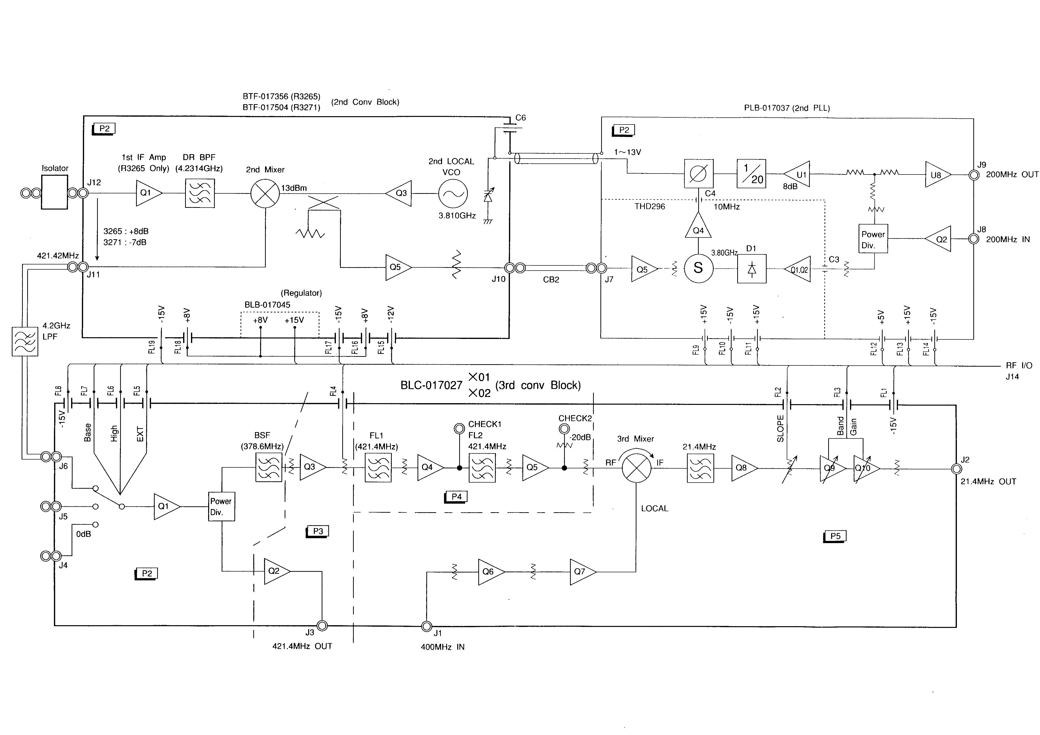
Functional description of block diagram
In the block diagram „2nd Conv Block“ is a voltage controlled oscillator (2nd LOCAL VCO) . The central target frequency of this VCO is 3810 MHz with a control range of +/- 4 MHz and amplified by Q3. This frequency is unregulated. To control this VCO a signal is fed back through a directional coupler and amplified by Q5.
At J8 there is a reference clock of 200 MHz generated by the internal reference oscillator (not shown). This is buffered once by Q1/Q2 and by U1 for further use.
In the THD296 board in the „2nd PLL“ block, one of the two 200 MHz references is used to generate 3800 MHz (by a step recovery diode D1 which acts as a frequency multiplier). This 3800 MHz and the fed back 3810 MHz of the VCO are mixed in „S“. The result is 10 MHz and 7610 MHz (7610 MHz are filtered out) and amplified by Q4. From the second 200 MHz signal path (amplified by U1) a reference frequency of 10 MHz is generated by a frequency divider (1/20). Both 10 MHz signals are compared phase wise in C4. The error signal (from C4) is used to control the VCO. Thus these assemblies form a phase locked loop (PLL).
Unfortunately, this is not my only issue. The THD296 assembly uses a step recovery diode to generate 3800 MHz from 200 MHz. However, it appears that the diode is broken, and there is no parts list or schematic for this particular assembly in the service manual.
While I plan to verify my findings by replacing the entire assembly with a working one, I intend to repair the original assembly by reverse-engineering the PCB and attempting to fix it. Another option would be to replace it by a modern frequency syntesizer with a double balanced mixer or directly replace the whole 2nd LO & PLL with a PLL module.
In the end
Update Beginning of 2024
The assembly was not defect. The re-tinning of the silver ink traces did the job, but one of the coils which biases the step recovery diode had a really small crack and didn’t contact properly.This happened probably whilst I retinned the whole PCB.
After this step and recovering the second dead unit (which had a power supply fault) I was able to also repair the second unit I’ve got. The unit in the end was able to run through all of the internal calibration procedures and works reasonably well in frequency counter mode without the enormous frequency drift from before.
Attached you can find my personal notes during the repair and the partly reverse engineered circuit diagram of the power supply.
Hallo Sebastian,
das ist ein interessanter und sehr hilfreicher Beitrag, „Repair of Advantest R3265A“.
Vor einigen Wochen habe ich mir auch diesen Spec. gekauft.
Vermutlich wird auch mein Gerät diesen Fehler haben.
Ich konnte es noch nicht testen.
Beim letzten Funktionstest mit einem Frequenzsynthesizer hatte ich
geringe Frequenzabweichungen am Spec. bemerkt.
Ein paar Tage später, zum nächsten geplanten Testlauf, schaltete nach 5 Minuten Aufwärmbetrieb das Netzteil ab. Die Kontroll-LED, durch die Geräterückseite sichtbar, leuchtete nicht mehr.
Die CRT verdunkelte. Nur der Gerätelüfter lief weiter.
Hoffentlich ist nicht der Zeilentrafo defekt.
Ist dir ein Ausfall dieser Art bekannt?
Gruß aus dem Weserbergland
Frank
DF6AN
Hi Frank,
Ich habe noch einen zweiten bei dem ich das Netzteile repariert habe. Ich kann mal die Unterlagen dazu raussuchen. Ich habe auch teilweise den Schaltplan vom Eingang her reverse engineered. Auf jeden Fall noch einen Stoß Bilder.
Hinweis schonmal: viele Bilder beim zerlegen machen. Das Schaltnetzteil ist genau in der Mitte des gesamten Geräts.
Kannst du dein Gerät noch bedienen obwohl der CRT dunkel ist ? Eigentlich sollte das Netzteile „komplett“ aus sein wenn die status led am Ende nicht leuchtet.
Viele Grüße
Sebastian
Guten Tag,
Ich habe deinen ausgezeichneten Artikel über die Reparatur des R3265A gelesen.
Ich finde den zweiten Teil nicht.
Ich benötige Hilfe für meinen mit Problemen am Netzteil: es schaltet nur den Ventilator ein. Trotz des Servicehandbuchs kann ich nicht auf das Netzteil zugreifen.
Haben Sie ein Video oder eine demonstrative Beschreibung?
Danke für die Hilfe.
Paolo
Guten Tag,
nach langem Bemühen ist es mir gelungen, das Advantest R3265A zu öffnen und Zugang zur Platine des Netzteils zu erhalten.
Und dort bin ich ins Stocken geraten. Es gibt keinen Schaltplan oder etwas Ähnliches, anhand dessen man weitermachen könnte. Ich habe einen Blockschaltplan gefunden. Das Servicehandbuch ist keine Hilfe.
Ich suche den Schaltplan des Netzteils.
Kann mir jemand helfen?
Vielen Dank
Übersetzt mit DeepL.com (kostenlose Version)
Hi Paolo,
ich habe meine privaten Notizen sowie den reverse engineerten Schaltplan des Netzteils mit an den Beitrag angehaengt.
Es gibt keinen wirklichen Teil 2. Nur den Absatz ueber den Nachtrag.
Viele Gruesse Sebastian N.
Thank you for providing the power supply diagram. You’ve made me less blind.
Do you also have the voltage values to measure?
Thanks again.
Danke Sebastian,
ich glaube, es wird schwierig sein, das Netzteil zu reparieren. Ich habe festgestellt, dass die gesamte Leiterplatte unterhalb des Reglers M51995P und die beiden Widerstände (R12 und R13) buchstäblich durchgebrannt sind.
Ich habe die Spannung an Pin 16 des IC gemessen und 145 Volt festgestellt.
Hast du die Spannungswerte der Schaltung?
Ich glaube, dass eine Reparatur nicht sicher ist, daher überlege ich, eine neue Stromversorgungsplatine zu kaufen. Ich wäre daran interessiert, wenn du eine hättest.
Für ein anderes gleiches Gerät habe ich den Mixer beschädigt.
Danke für deine Hilfe.
Viele Grüße.
Paolo
Übersetzt mit DeepL.com (kostenlose Version)