Building a high-speed Ethernet interface from scratch can be a challenging but rewarding experience. As a hardware enthusiast, I set out to design and assemble my own Ethernet card using the Microchip LAN7430 chip.
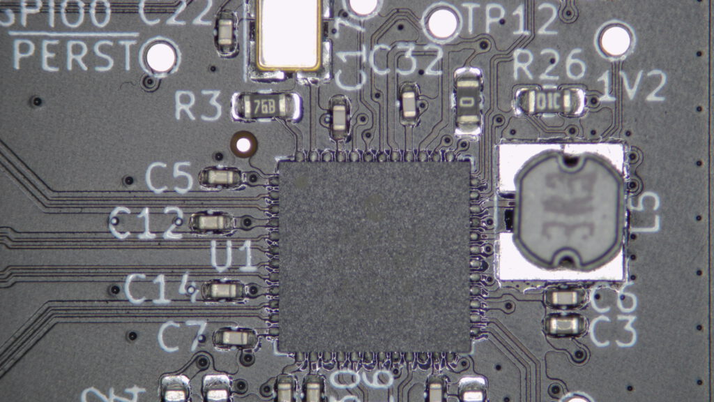
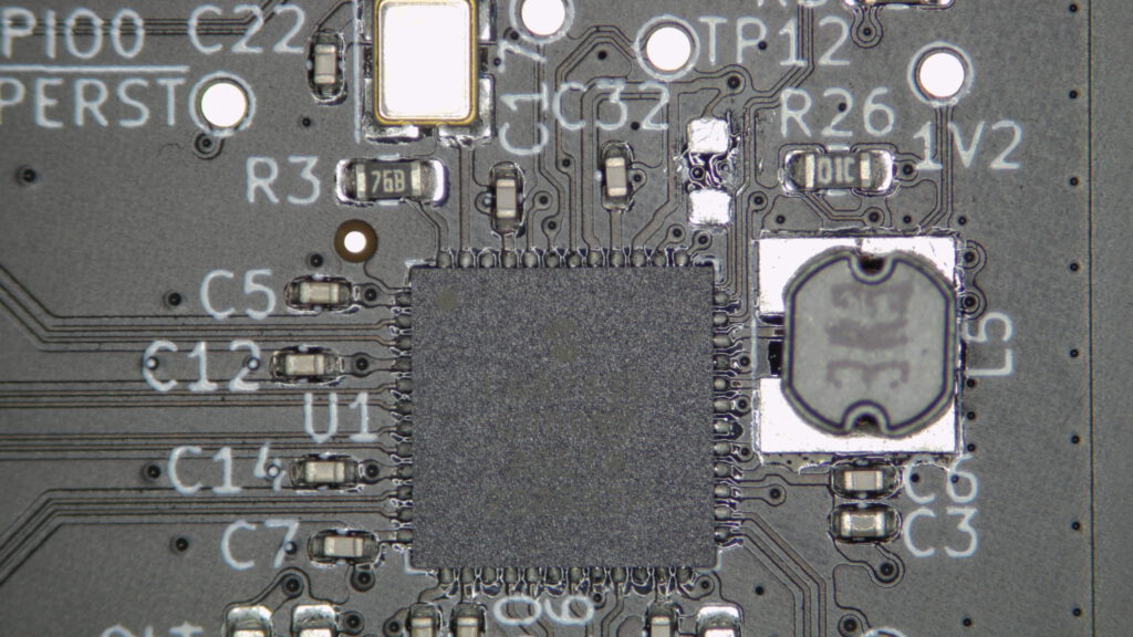
After spending countless hours researching and designing my PCB layout, I sent it off to be manufactured. Unfortunately, my plans hit a snag when the manufacturer couldn’t add a chamfer to the PCIe edge connector due to assembly issues. But I didn’t let that stop me. I assembled the RJ45 connector and inspected the PCB under a microscope, making sure there were no obvious issues.
But my problems didn’t end there. Upon trying to power up the board, I discovered a short circuit on the 3V3 rail caused by a pull-up 0 ohm resistor. It turned out that the fault was due to a mistake I made, as the resistor was actually marked as „do-not-populate“ but I mistakenly included it in the Pick’n’place file. After removing the resistor, my Ethernet card successfully showed up in the PCI enumeration list.
Feeling proud of my progress, I designed a draft for a PCIe bracket with two SMA connectors to bring out the IEEE 1544.8 PTP signals. A friend with a 3D printer helped me produce a prototype, and I added it to my project.
In the future, I plan to test the JTAG boundary scan feature on the PCB with an Olimex debugger and different software. But for now, I’m happy with the card’s Ethernet link, which is capable of speeds of up to 940 Mbit/s, and I’m confident that it will perform well in future tests.
However, I still have some work to do on the LED configuration. While the link status indication works perfectly, the activity indication still needs some tweaking. But that’s all part of the fun of building your own hardware from scratch – you get to troubleshoot and fine-tune until you get the perfect result.
Miscellaneous Measurements
As I was working on the Ethernet card project, I found myself measuring all sorts of miscellaneous things, just out of curiosity. It was an exciting opportunity to test different features and components of the board, and I was eager to see how everything worked.
Phase Noise
I also conducted a phase noise measurement of the oscillator (25MHz) in comparison to a measurement of the 300MHz reference signal of the measuring spectrum analyzer HP8560A.
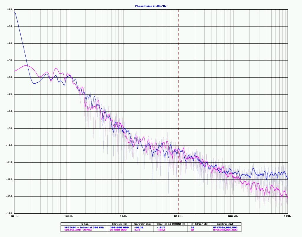
A phase noise plot describes the short-term instability of a signal. It is a graphical representation of the noise power density of a signal as a function of frequency offset from the carrier frequency. The plot shows how much noise is present in the signal at different frequency offsets, with higher offsets indicating longer timescales. Phase noise is an important parameter in many applications, especially those involving high-precision timing, frequency synthesis, and communication systems. A lower phase noise means that the signal is more stable and accurate, and is therefore better suited for these applications.
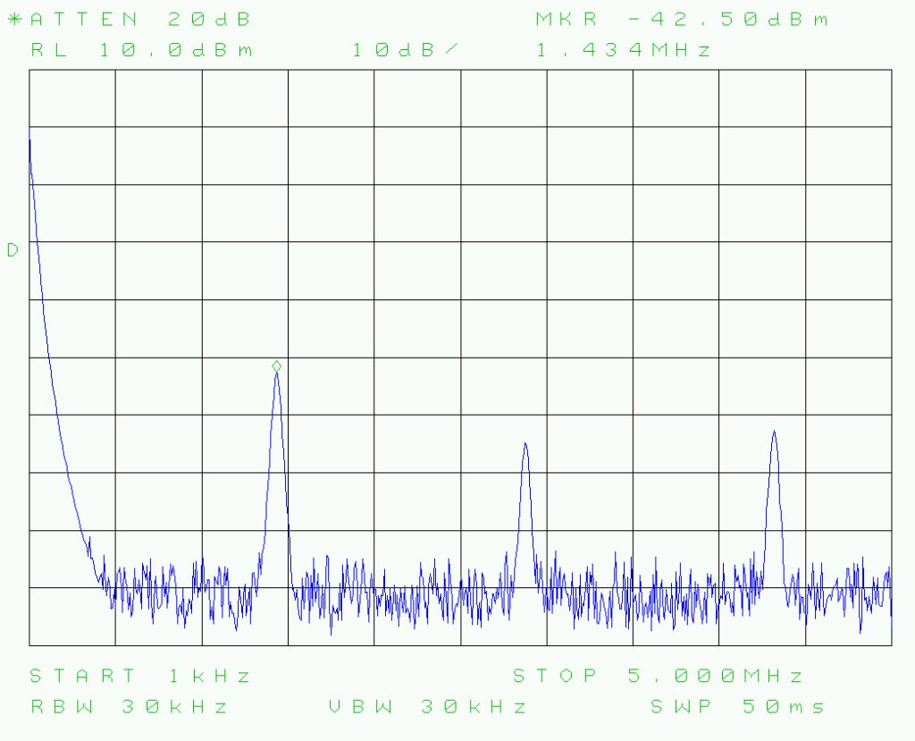
Integrated Switching Regulator
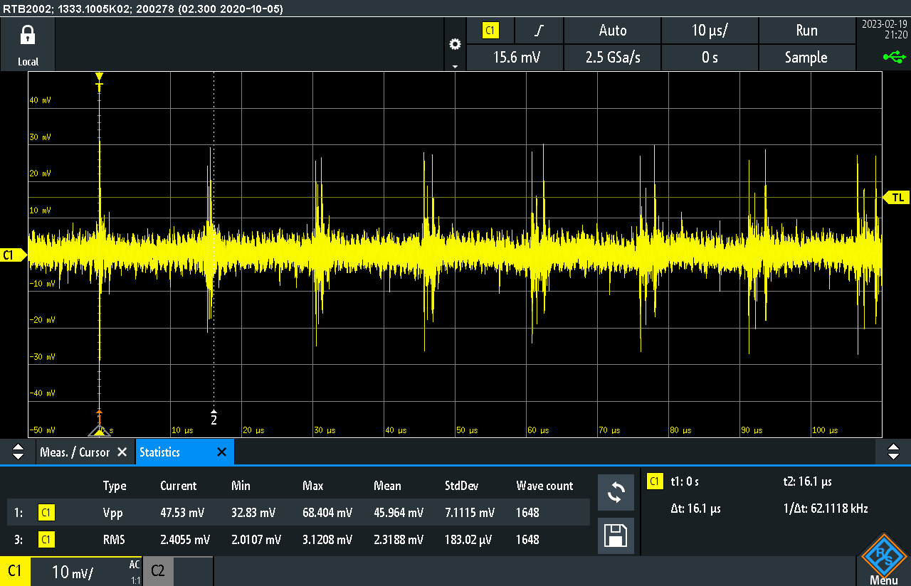
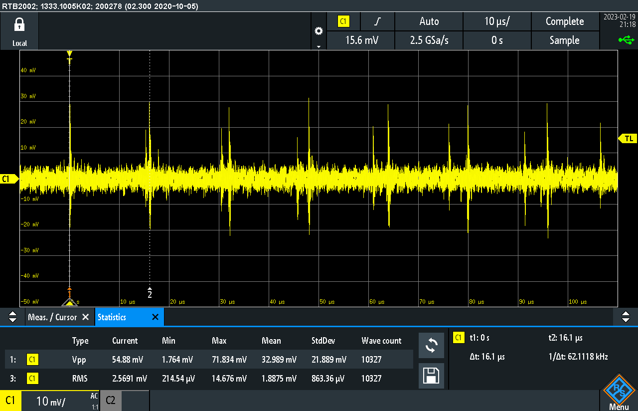
In addition to my other measurements, I decided to take a look at the frequency of the integrated switching regulator and explore the ripple voltage. Using an oscilloscope, I measured the frequency of the regulator to be around 1.434 MHz, which was in the expected range. I then examined the ripple voltage on the regulator output, and found it to be within the acceptable range for my application. While it may not have been necessary for the overall functionality of the Ethernet card, exploring these types of measurements can provide valuable insights into the performance and stability of the power supply system.
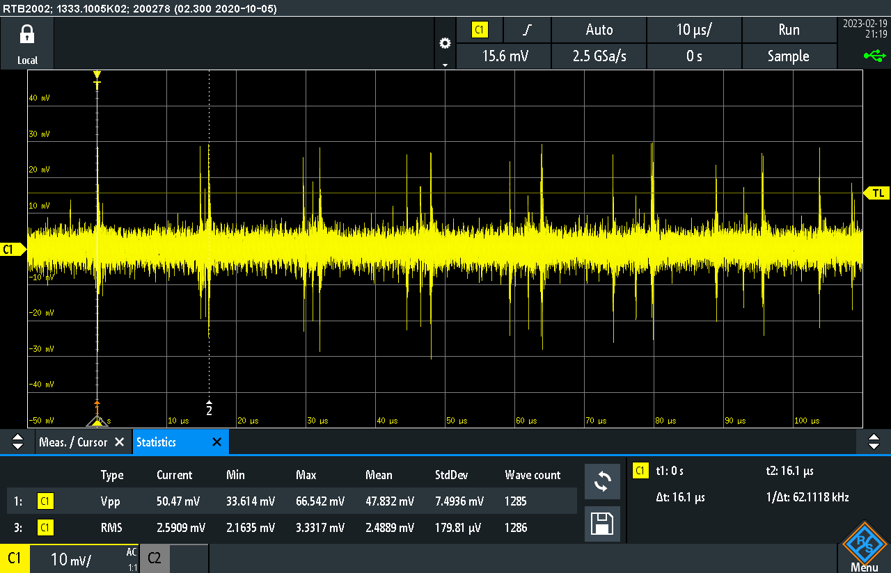
switching regulator